Working with Flexible Circuits
 Flexible circuits were first introduced as a replacement for wire harnesses. The earliest versions date back to World War II. Today, flex and rigid flex circuits are filling an important role across multiple industries, include applications in the medical, automotive, and telecom fields.
Even though they are a smaller part of the circuit board industry, flex and rigid flex circuits have been growing in popularity over the last decade, and for good reason. These circuits are made to be thin, flexible and durable. However, in addition to the opportunities that come with flex and rigid flex circuits, there are also challenges. Generally, these occur with the processing part of the technology.
Characteristics of Flex and Rigid Flex Circuits
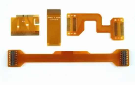
Flex and rigid flex circuits have become a go-to solution for a variety of applications, because they offer capabilities that simply aren’t available from alternatives. They can be manufactured to very thin specifications, and they will survive bending and folding without error. These circuits can be run over long distances to make a connection. For example, some users have designed 14 – 18-foot flexible cables.
Some of the most sought-after features of flex and rigid flex circuits include the following:
- Thin core capability
- Improved dielectric constant
- Low Dk and low Df critical concerns
- Ultra-fine line capable – L/S decreasing to less than 15 micron
- Shorter interconnect distances
Flexible circuits have the same capabilities of their rigid counterparts, including repeatability, reliability, and high density. In addition, they have characteristics that make them more versatile than rigid circuits. For example, they are – of course – flexible, and they can resist vibration more effectively. One of the most popular features of flexible circuits is that they can be designed into three-dimensional configurations.
Rigid flex circuits combine the best features of flexible and rigid circuits to meet a variety of needs. The rigid areas make it possible to mount stationary components, while the flexible areas can be custom configured and serve as protection against vibration.
Despite the fact that flex boards can be extremely thin, they are remarkable durable. These circuits are capable of repeating the same bends through millions of cycles without interruption. This is a critical point when it comes to applications that face intense vibration and/or acceleration.
Challenges with Flex and Rigid Flex Circuits
The conductors on flex boards are covered with polyimide. This solution offers more complete protection for the circuit than a solder mask. One of the first challenges you are likely to face is the fact that polyimide films are difficult to activate, as they are inert materials. This creates seeding issues with the Pd catalyst. Though they are extremely reliable, getting metallization to adhere and cover polyimide is an issue that must be overcome.
Another challenge you may face is the need to adjust your chemical practices if you are relying on an adhesive base flex. It is common for adhesives – particularly acrylic adhesives – to falter or completely succumb to attacks when exposed to highly alkaline solutions. If your adhesive flex application is impacted by this issue, you may choose to rely on plasma alone, instead of alkaline permanganate.
Don’t let the challenges of flex and rigid flex circuits prevent you from enjoying the benefits of this technology. RBP Chemical has the knowledge and resources to diagnose and correct issues impacting Flex and Rigid Flex Circuits. Contact us to learn more.


